تقنية تحديد المواقع بتقنية النطاق العريض للغاية
يقدم هذا الكتاب الأبيض بشكل أساسي المبادئ واختيار المخطط وطرق التنفيذ
استخدام تقنية تحديد المواقع ذات النطاق العريض للغاية في سيناريوهات تطبيق مختلفة.
في الوقت الحالي، يمكن تقسيم تقنيات تحديد المواقع السائدة إلى أربعة أنواع بناءً على مبادئها:
الصوت والضوء والكهرومغناطيسية وUWB
تسرد وثيقة التصميم هذه المزايا والعيوب الرئيسية لكل مبدأ بعد التحليل الأساسي. تشرح الوثيقة بشكل أساسي تصميم النظام وطريقة التنفيذ باستخدام تقنية تحديد المواقع فائقة النطاق العريض UWB لتحديد المواقع.
الفصل الأول
مبدأ التموضع
من حيث المبدأ، تشمل أساليب تحديد المواقع الحالية بشكل رئيسي الصوت والضوء والكهرباء والمغناطيسية. كما توجد الملاحة بالقصور الذاتي، ولكن نظرًا لعدم نضج هذه التقنية ومحدودية تطبيقاتها، فلن نناقشها هنا.
صوت
يقيس هذا الجهاز المسافة بشكل رئيسي من خلال جمع زمن انتقال الموجات فوق الصوتية في الهواء. عادةً ما يكون جهاز الإرسال مكبر صوت، وجهاز الاستقبال ميكروفونًا (مثل الهاتف المحمول). يرسل جهاز الإرسال معلومات ثابتة، ويحسب جهاز الاستقبال زمن انتقال البيانات ويحولها إلى مسافة. بعد ذلك، يُحدد الموقع باستخدام أسلوبي النقطتين أو الثلاث نقاط.
المميزات:
يتميز بدقة تحديد مواقع عالية جدًا، تصل إلى مستوى السنتيمتر. كما يتميز ببنية بسيطة نسبيًا، وقدرة اختراق عالية، وقدرة قوية على مقاومة تداخل الموجات فوق الصوتية نفسها.
العيوب:
إن التوهين الجوي مرتفع، وهو غير مناسب للأحداث واسعة النطاق، كما أن تأثير المسارات المتعددة والانتشار غير المباشر يسببان أخطاء كبيرة في تحديد مدى الانعكاس، مما يتطلب تحليلًا دقيقًا وحسابًا لمرافق الأجهزة الأساسية، كما أن التكلفة مرتفعة للغاية.
نطاق التطبيق:
تُستخدم تقنية تحديد المواقع بالموجات فوق الصوتية على نطاق واسع في الأقلام الرقمية واستكشاف البحار. كما تُستخدم هذه التقنية لتحديد المواقع داخل المباني لتحديد مواقع الأجسام في الورش غير المأهولة.
تحديد موضع الضوء المرئي
يمكن تطوير هذه التقنية باستخدام مصابيح LED. تُرسل هذه المصابيح إشارات وامضة عالية التردد. بعد استقبالها، يحسب جهاز الاستقبال زمن الرحلة لقياس المسافة، ثم يحصل على معلومات الموقع.
المميزات:
نطاق ديناميكي كبير، قادر على الاتصال بمعدلات عالية.
العيوب:
بسبب قصر طول موجة الضوء وضعف قدرته على الحيود، من السهل حجبه. أما الطريقة الأخرى، فتتمثل في استخدام تقنية التعرف على الصور لمقارنة معلومات الصورة في الوقت المناسب مع تلك الموجودة في قاعدة البيانات لتحديد الموقع. أما العيب، فهو أن معالجة الصور تستغرق وقتًا طويلاً وتستهلك طاقة كبيرة.
تحديد موقع المجال المغناطيسي
الأرض نفسها مغناطيس عملاق، يُنشئ مجالًا مغناطيسيًا أساسيًا بين القطبين الشمالي والجنوبي الجغرافيين. ومع ذلك، قد يتأثر هذا المجال المغناطيسي للأرض بالأجسام المعدنية، وخاصةً في المباني ذات الهياكل الخرسانية المسلحة. تتداخل مواد البناء (الهياكل المعدنية) مع المجال المغناطيسي الأصلي وتُشوّهه، مما يجعل لكل مبنى نسيجًا مغناطيسيًا فريدًا. بمعنى آخر، يتشكل مجال مغناطيسي داخلي منتظم داخل المباني.
من خلال جمع معلومات المجال المغناطيسي في الحقل مسبقًا، ثم مقارنتها بالمعلومات التي جمعها مقياس المغناطيسية في جهاز تتبع (مثل الهاتف المحمول)، يمكننا الحصول على معلومات موقع دقيقة. نظريًا، يبلغ فرق المجال المغناطيسي في مواقع مختلفة ميكروثانية، وهو أمر لا يمكن اكتشافه بأدوات القياس العادية. لكن هذا المجال المغناطيسي الداخلي المشوه بسبب تداخل المبنى يعزز فرق الإشارة المغناطيسية، مما يجعل الحصول على البيانات المغناطيسية داخل الغرفة ممكنًا ويحسن دقة تحديد الموقع بشكل غير مباشر. نظرًا لأن نمط المجال المغناطيسي لكل مساحة صغيرة في الغرفة فريد من نوعه، يمكن تحديد موقع الهاتف المحمول بدقة عن طريق مطابقة خصائص المجال المغناطيسي للمنطقة مع قاعدة بيانات المجال المغناطيسي في النظام، وعادةً ما تكون الدقة حوالي مترين.
مع ذلك، إذا تغير تصميم المباني المجاورة، مثل حركة المركبات، فسيتغير المجال المغناطيسي أيضًا، وسيصعب تقييم دقته. تتطلب هذه الطريقة معايرة متكررة للمجال المغناطيسي، ولا يُنصح بها.
تحديد موقع الموجات الكهرومغناطيسية
قوة الإشارة
من التطبيقات الشائعة استخدام جهاز تتبع بلوتوث وبوابة بلوتوث، ويمكن تحديد موقعهما بحساب قوة الإشارة. يستخدم نظاما B-Fixed وB-Mobile التابعان لشركتنا هذا النظام. ومن أهم مزاياه انخفاض تكلفته وسهولة تصميمه، مع دقة تتراوح بين مترين وثلاثة أمتار كحد أقصى. ويُستخدم بشكل رئيسي لتحديد المواقع الإقليمية للأصول والأفراد.
آو آو
يُشار إليه عادةً باسم تقنية Bluetooth Angle of Arrive.
ميزة:
تكلفة منخفضة للمحطة، تحتاج فقط إلى نشر بوابة واحدة ودقة تحديد المواقع العالية.
العيوب:
تغطية محدودة، ونصف قطر التغطية مساوٍ لارتفاع البوابة. يجب تثبيت البوابة بدقة، ويجب عدم اهتزازها أثناء الاستخدام، وإلا سيؤثر ذلك على دقة تحديد الموقع.
النطاق العريض للغاية
وقد اقترحت وكالة مشاريع الأبحاث الدفاعية المتقدمة ولجنة الاتصالات الفيدرالية تعريفات مختلفة للنطاق العريض للغاية، ولكن فقط مع اختلافات دقيقة في المعايير.
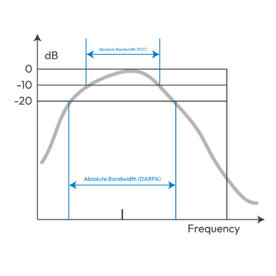
مواصفات النبضة الضيقة للنطاق الأساسي UWB:
IR-UWB (راديو النبضة-UWB):
يُرسل هذا النظام مباشرةً عبر الهوائي دون تعديل الموجة الجيبية. يتميز هذا النوع من الأنظمة بالبساطة، والدقة، والتكلفة المنخفضة، واستهلاك الطاقة المنخفض، ومقاومة تعدد المسارات، وفعالية الاختراق. وقد تم اعتماده لاحقًا في معيار 802.15.4a.
تعديل الموجة الحاملة للنطاق الترددي:
DS-UWB (الوصول المتعدد بتقسيم الترميز التسلسلي المباشر) و MB-UWB (الإرسال المتعدد بتقسيم التردد المتعامد متعدد النطاقات).
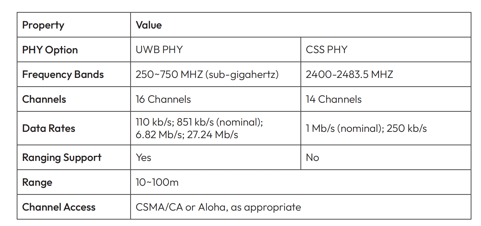
من بينها، يحدد IR-UWB طبقتين فيزيائيتين في مواصفات IEEE 802.15.4a-2007: الأولى هي تقنية CSS (التي تقدمها شركة Nanotron الألمانية، التي تعمل على تقنية تحديد المواقع ذات النطاق الضيق 2.4G)، والأخرى هي تقنية IR-UWB.
هيكل حمولة النطاق العريض للغاية: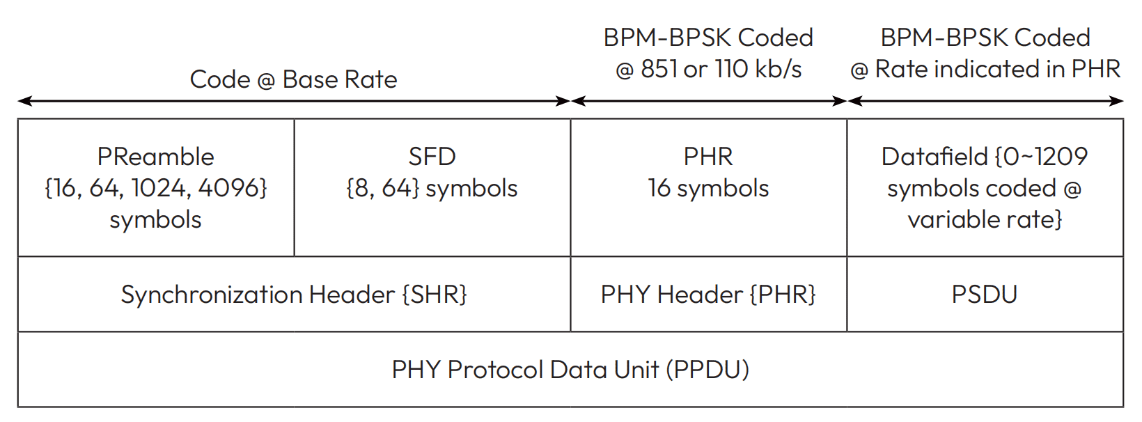
تعديل
BPM-BPSK:
إنه يجمع بين BPM (تعديل موضع الانفجار) وBPSK (مفتاح التحول الطوري الثنائي).
نطاق التردد/القناة العاملة:
الجدول العالمي لتوزيع النطاق الترددي المتاح هو كما يلي
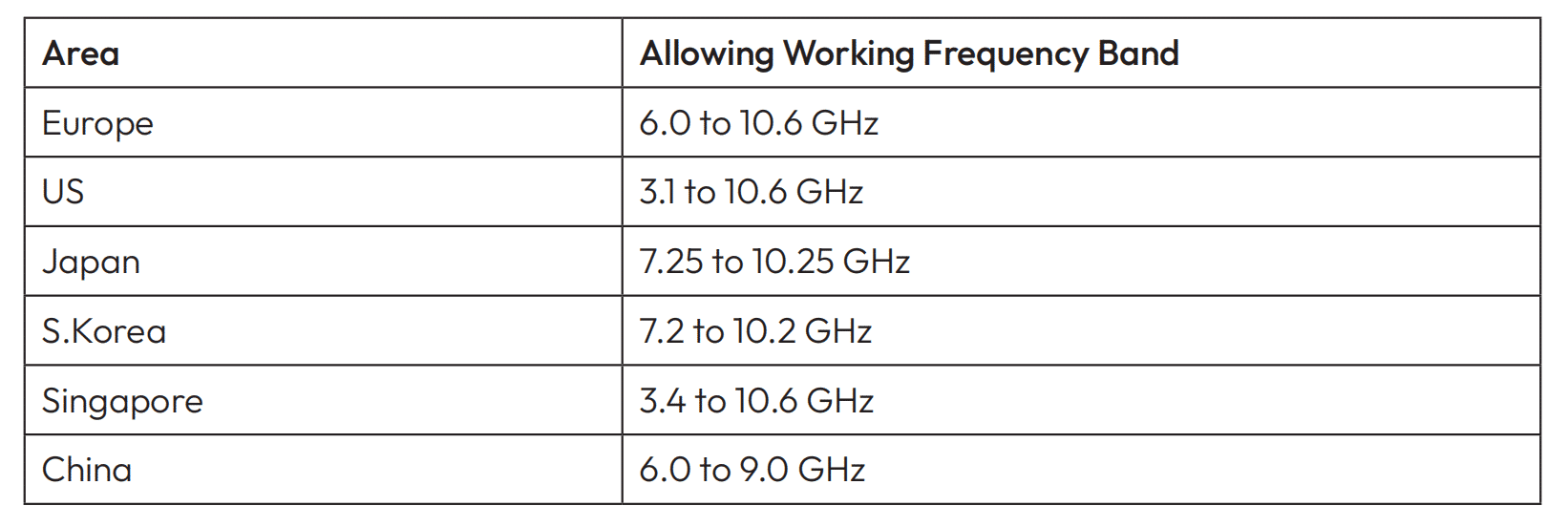
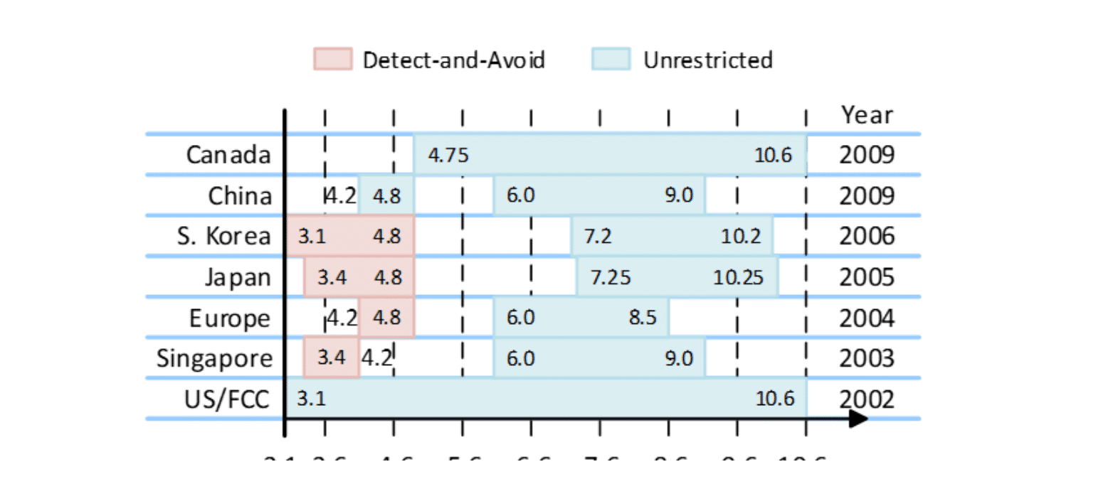
قسم القناة

يتضمن تقسيم القنوات نوعين من القنوات: ٥٠٠ ميجاهرتز و١ جيجاهرتز. حاليًا، تُستخدم قنوات ٥٠٠ ميجاهرتز بشكل رئيسي، أي القنوات ١، ٢، ٣، و٥.
قوة الإخراج واللوائح:
وفقًا للوائح لجنة الاتصالات الفيدرالية (FCC)، الحد الأقصى هو -41dBm/MHz.
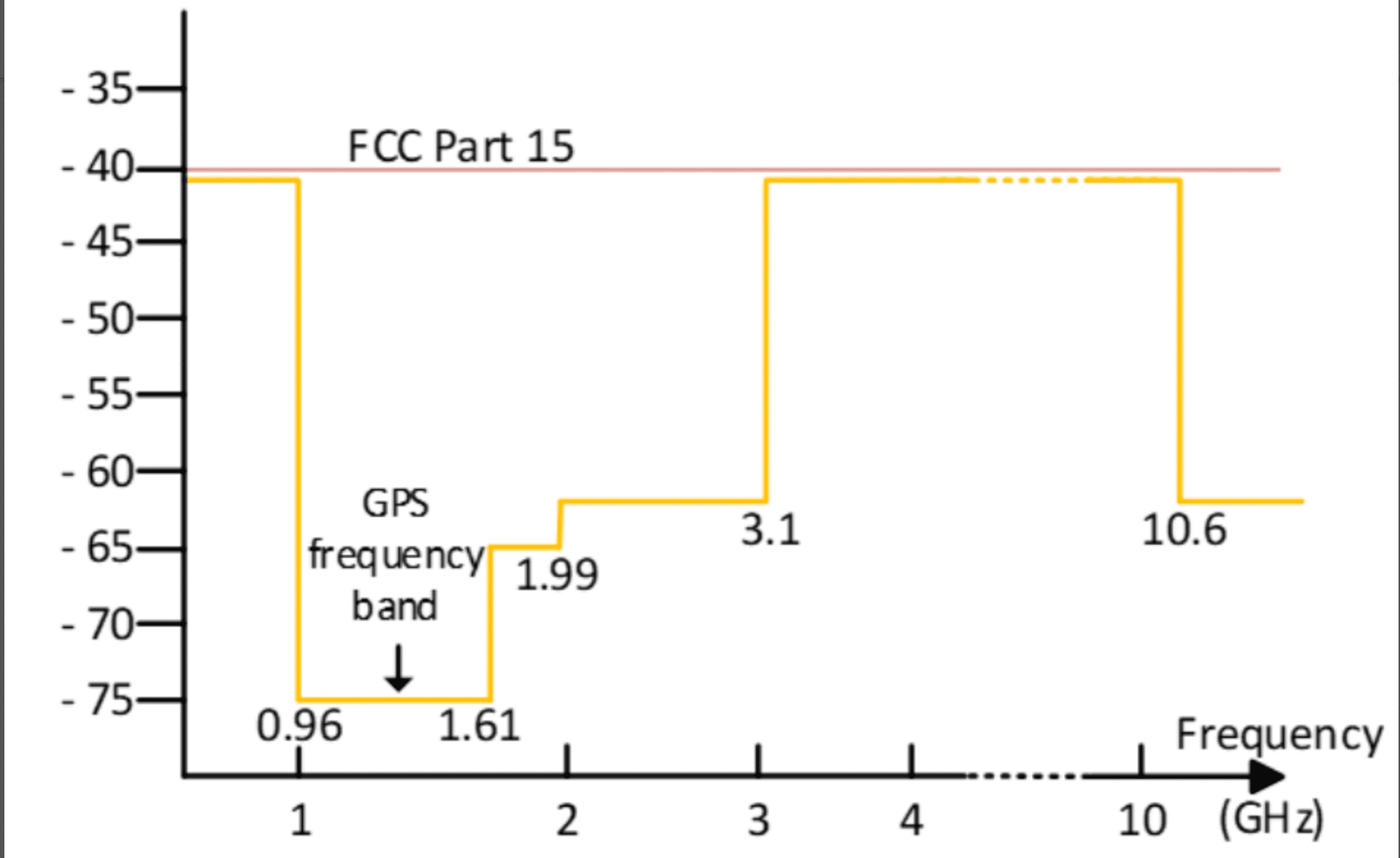
قواعد القوة في الصين:

الفصل الثاني
مقارنة بين تقنيات تحديد المواقع
مقارنة بين تحديد المواقع بتقنية UWB وتحديد المواقع بتقنية Bluetooth AoA
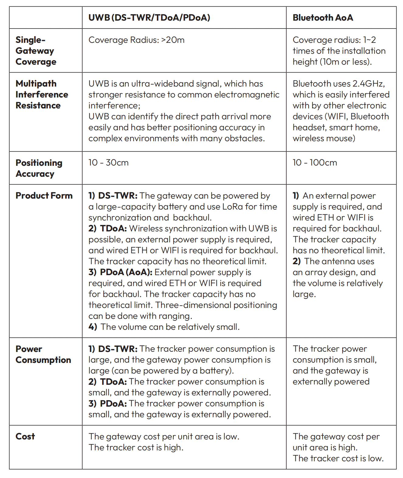
مقارنة بين تحديد المواقع بتقنية UWB-AoA وتحديد المواقع بتقنية Bluetooth AoA
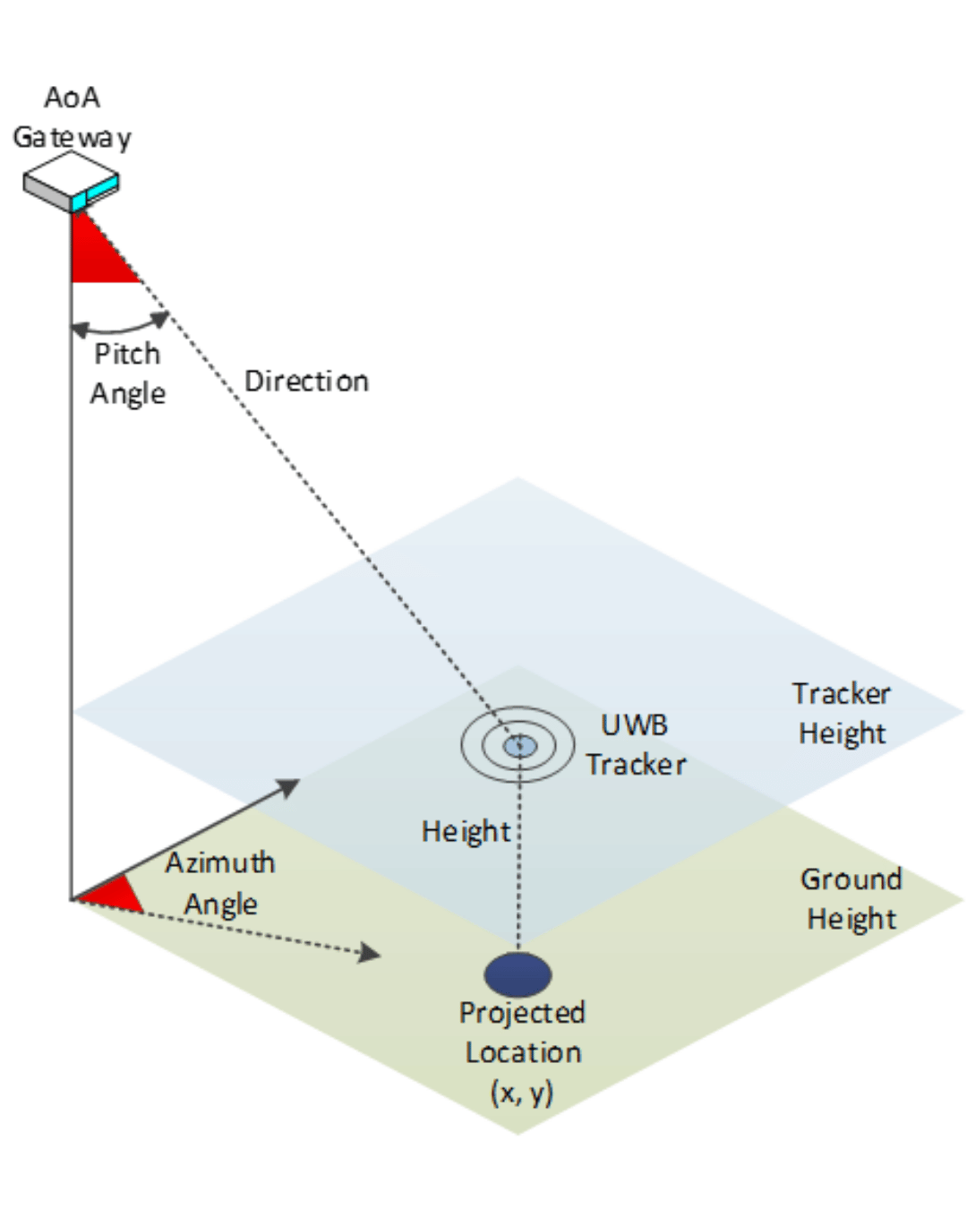
مقارنة المبادئ:
بلوتوث AoA:
تقيس هذه الطريقة زاوية الإشارة من بوابة واحدة فقط، وليس المسافة. كما تفترض أن ارتفاع جهاز التتبع ثابت، وتُسقط موقعه من تقاطع الزاوية والارتفاع. قد يؤثر رفع جهاز التتبع وخفضه بشكل كبير على دقة تحديد الموقع.
UWB-AoA:
تقيس هذه الطريقة كلاً من الزاوية والمسافة بدقة سنتيمترية، وهي أكثر دقة. كما يمكنها تحديد موقع جهاز التتبع في ثلاثة أبعاد.
مقارنة الهوائي:
بلوتوث AoA:
تستخدم هذه الطريقة مصفوفة هوائيات، عادةً ما تحتوي على 16 أو 64 هوائيًا، ومفاتيح تردد لاسلكي لحساب زاوية وصول الإشارة والمسافة من أوقات وصول متعددة. يمنع تصميم مصفوفة الهوائيات المعقد تصغير بوابة بلوتوث AoA. كما أن للبوابة متطلبات تركيب صارمة ومنطقة تغطية محدودة تبلغ حوالي ضعف نصف قطر الارتفاع.
UWB-AoA:
تستخدم هذه الطريقة عادةً هوائيين وطريقة فرق الطور PDoA لحساب الزاوية المثلى. تتطلب هذه الطريقة أن تكون المسافة بين هوائيي الاستقبال مساويةً للطول الموجي، أو λ/2. بالنسبة للقناة 5 (6489.6 ميجاهرتز)، تكون المسافة بين هوائيات التثبيت 2.08 سم، وبالنسبة للقناة 9، تكون المسافة بينهما أقرب. يسمح هذا بتصغير PDoA، ولذلك يمكن استخدامه في تطبيقات مثل الهواتف الذكية، وأقفال الأبواب الذكية، وأجهزة التحكم المنزلية الذكية.
الفصل الثالث
تكنولوجيا النطاق العريض للغاية
ميزات النطاق العريض للغاية
- يغطي UWB نطاقات التردد 3G~5G، و6G~10G، ومجموع نطاقات التردد 7G، وله قناة واحدة
عرض النطاق الترددي أكثر من 500 ميجا هرتز. - طاقة منخفضة. وفقًا للوائح لجنة الاتصالات الفيدرالية (FCC) وغيرها، تبلغ طاقة خرجه -41 ديسيبل/ميلي واط. بناءً على قناة واحدة بتردد 500 ميجاهرتز، تبلغ طاقة قناته -14.3 ديسيبل/ميلي واط.
- النبضة القصيرة جدًا، ومدتها بضعة أعشار النانو ثانية.
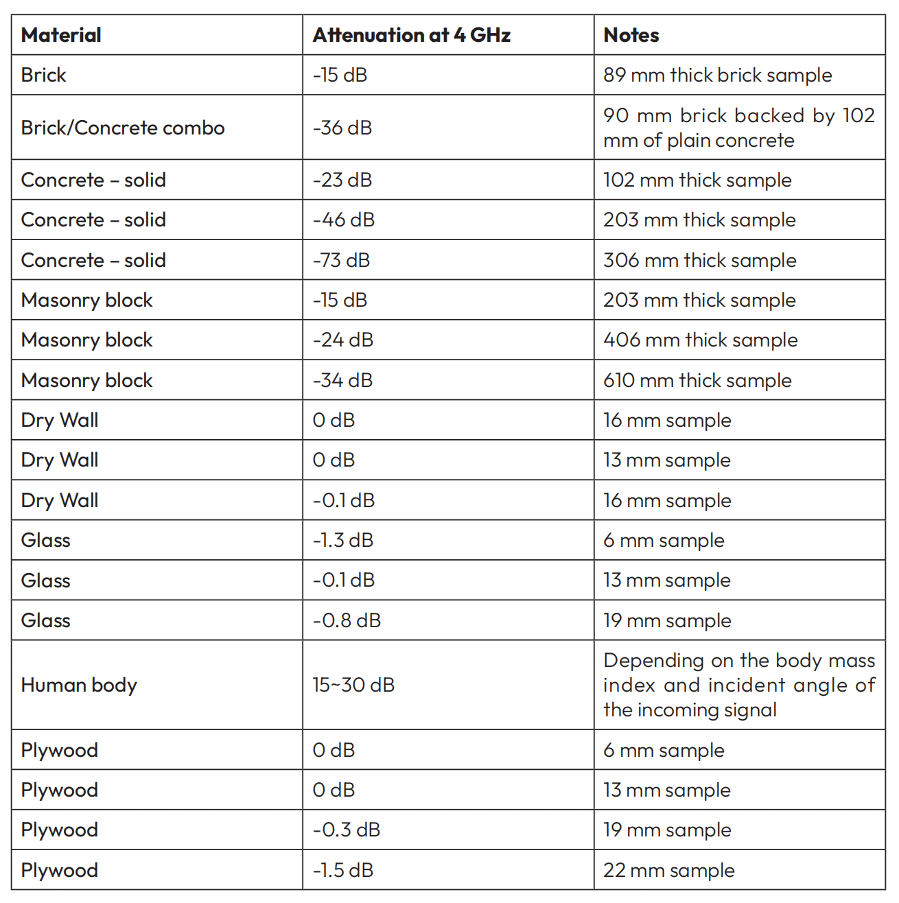
- اختراق الجدار: يمكنه اختراق الجدران بشكل فعال ولكنه سوف يسبب بعض التوهين للإشارة.
يوضح الجدول أدناه التوهين في الإشارة الناتج عن اختراق الجدار عند العمل على القناة 2 (مع 4 جيجاهرتز كتردد مركزي).
تحديد المسارات المتعددة
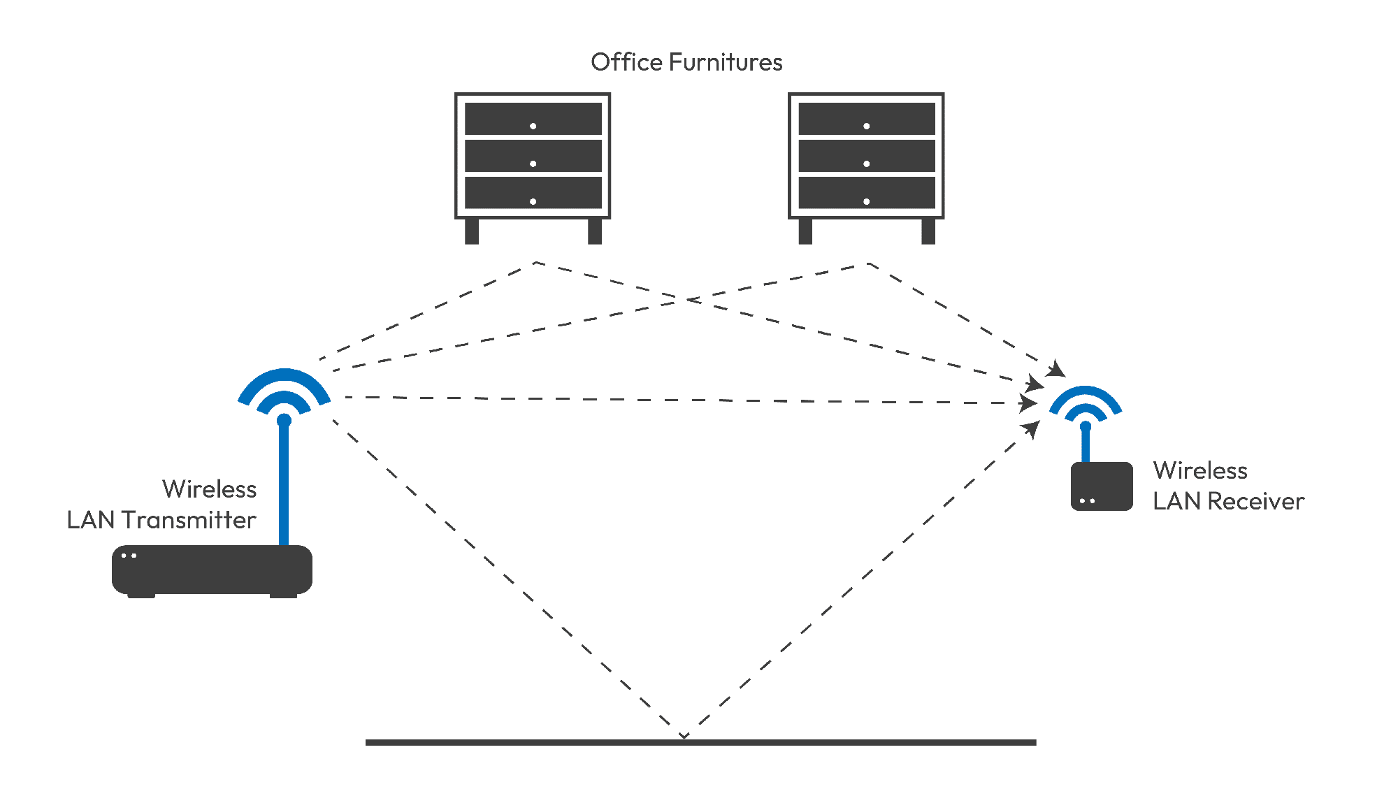
يمكن للموجات الكهرومغناطيسية أن تنتقل مباشرةً من المُرسِل إلى المُستقبِل، أو أن تنعكس إلى الهدف. في الاتصالات ضيقة النطاق، عادةً ما تُعالَج الإشارة الأقوى قوةً، والتي قد لا تكون الإشارة الأولى التي تصل.
في اتصالات النطاق العريض للغاية (UWB)، يُمكن تحديد أول إشارة تصل (المسار الأول) بدقة بناءً على فارق التوقيت. ولكن عند وصولها مباشرةً أو عبر الاختراق، لا يُمكننا سوى افتراض أن أول إشارة متعددة المسارات هي الإشارة المباشرة التي نحتاجها.
كما هو الحال مع جميع الموجات الكهرومغناطيسية الأخرى، لا تستطيع تقنية UWB اختراق المعدن.
دقة
تتضمن الدقة ثلاثة جوانب رئيسية: دقة تحديد المدى، ودقة مزامنة الوقت، ودقة تحديد الموقع. وتتأثر دقة تحديد المدى بشكل رئيسي بعاملين: خوارزمية تحديد المدى ودقة الساعة المستخدمة.
- دقة تحديد المدى: يقوم DS-TWR بتقليل الخطأ الناتج عن انحراف الساعة.
- دقة مزامنة الوقت: في نظام تحديد المدى، مذبذب بلوري معوض لدرجة الحرارة على مدار الساعة 0.5PPM (TCXO)
يمكن استخدامها لتحقيق دقة أفضل. يمكن التحكم بدقة القياس في نطاق ١٠ سم.
يمكن تحسين الدقة باستخدام TCXO.في نظام تحديد المواقع اللاسلكي UWB، يتم دعم كل من تحديد المدى وTDoA. في TDoA، يجب مزامنة جميع بوابات تحديد المواقع لاسلكيًا. يتمتع النظام بدقة مزامنة تبلغ 0.3 نانوثانية.
بالمقارنة مع طريقة المزامنة السلكية، فإن النظام اللاسلكي أبسط بكثير ويمكن توسيعه دون حدود، ولا يقيده المسافة السلكية. كما أنه يبسط صعوبة تنفيذ المشروع.
- دقة تحديد المواقع: تبلغ دقته 30 سم. تتأثر دقة تحديد موقع النظام بعدة عوامل.
العوامل البيئية، وليس فقط دقة قياس المسافة البالغة 10 سم. لا يمكن تحقيق دقة تحديد الموقع البالغة 10 سم إلا في بيئة مثالية دون أي تدخل في المختبر. أي اضطراب في الإشارة قد يُسبب انحرافًا عن النظام.
الفصل الرابع
حول تحديد المواقع
ميزات النطاق العريض للغاية
يُختار بُعد تحديد الموقع بناءً على حالة الاستخدام والوضع في الموقع. يُستخدم المشهد ذو البعد الصفري بشكل رئيسي لاكتشاف الدخول والخروج. أما المشهد أحادي البعد، فهو مشهد ذو نسبة عرض إلى ارتفاع غير متناسبة، مثل مشهد النفق، ويُستخدم أيضًا في المصانع. في المشهد أحادي البعد، يُحاذى الهدف الموضعي مع خط مستقيم. يُستخدم المشهد ثنائي الأبعاد لتحديد إحداثيات XY دون معلومات الارتفاع، بينما يتضمن المشهد ثلاثي الأبعاد معلومات الارتفاع. مع ذلك، يتطلب هذا المشهد وجود فرق في ارتفاع المرساة أثناء تثبيت النظام لضمان دقة معينة للمحور Z.
صفري الأبعاد
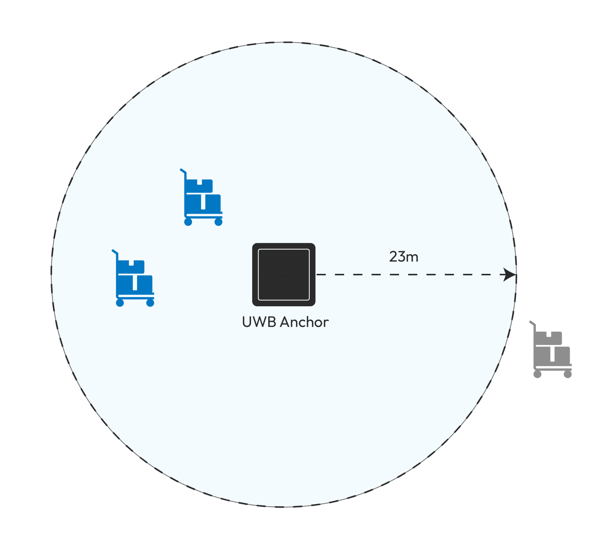
في تحديد المواقع بتقنية النطاق العريض للغاية (UWB)، يُحقق تحديد المواقع الصفرية الأبعاد بشكل أفضل من خلال تحديد المدى، والذي يُستخدم لتحديد المسافة، مثل بُعد الجهاز عن المرساة. ويُعتبر الجهاز قد دخل منطقة الصفر الأبعاد.
أحادي البعد
يمكن تحقيق تحديد المواقع أحادي البعد باستخدام ToF أو TDoA أو تقنية AoA المدمجة.
حتى عندما لا يكون متتبع UWB على الخط المستقيم الذي يربط بين المرسين، فإنه يمكن أن يكون على هذا الخط المستقيم.
الموقع الفعلي:
![]()
نتيجة التموضع:
![]()
ثنائي الأبعاد
سيعرض تحديد المواقع ثنائي الأبعاد إحداثيات XY لموقع الهدف. إذا تم تثبيت المراسي على نفس الارتفاع، فلن تتأثر نتائج تحديد المواقع بارتفاع تثبيت أجهزة التتبع.
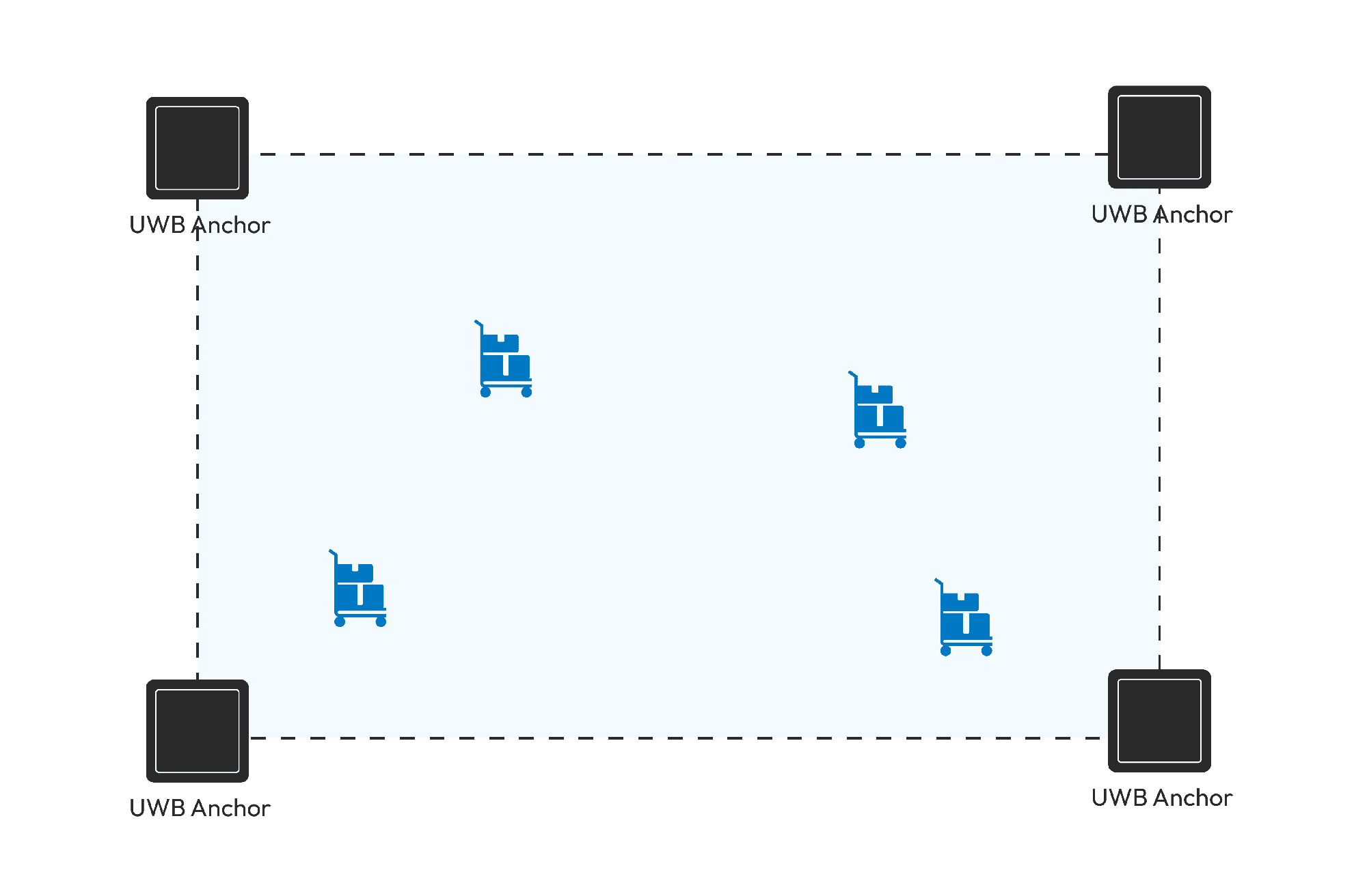
ثلاثي الأبعاد
إن نتيجة تحديد المواقع ثلاثية الأبعاد هي إحداثيات XYZ للهدف. وهناك طريقتان لتحقيق ذلك. تعتمد الأولى على قياس المسافة، والتي تتطلب فرق الارتفاع بين المراسي. وتعتمد الثانية على زاوية الهجوم، والتي تتطلب دقة زاوية عالية على المحور Z لضمان دقة إحداثيات Z.
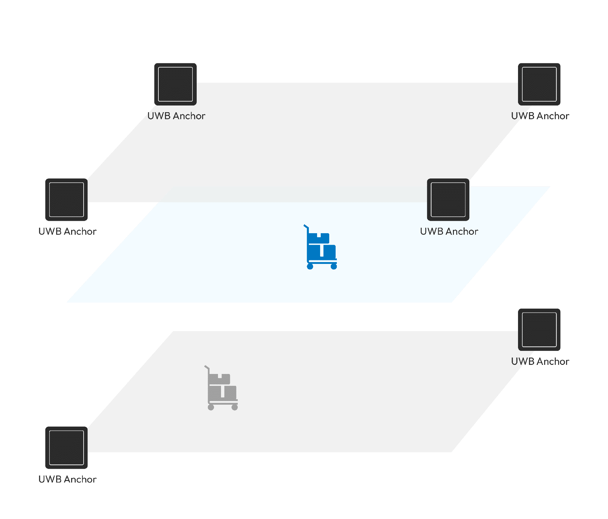
طريقة تحديد المواقع
حاليًا، يعتمد تحديد المواقع بتقنية النطاق العريض للغاية (UWB) بشكل رئيسي على تحديد مدى TOF، وتحديد موقع TDoA، وتحديد موقع AoA. تعمل الطريقتان الأوليتان بشكل مستقل، بينما عادةً ما تُدمج طريقة AoA الثانية مع تحديد مدى TOF أو TDoA.
تحديد المواقع ToF
يعتمد تحديد موقع ToF على المدى. يبدأ متتبع النطاق فائق العرض (UWB) عملية تحديد المدى مع كل مرساة مطلوب تحديد موقعها. بعد اكتمال تحديد المدى، يُحسب الموقع. في الوضع صفري الأبعاد، يتطلب تحديد المدى مرساة واحدة فقط، وفي الوضع أحادي البعد، يتطلب تحديد المدى مرساتين على الأقل. أما في الوضع ثنائي الأبعاد، فيتطلب تحديد المدى عادةً ثلاث مرساة أو أكثر، ولكن في بعض الأوضاع الخاصة، يكفي مرساتان. أما في الوضع ثلاثي الأبعاد، فيتطلب تحديد المدى بأربع مرساة.
بالنسبة للحالات أحادية البعد، يتم وضع المرساة في الأعلى، ويتم تحديد نطاقها باستخدام مرساة واحدة فقط لتحقيق وضع أحادي البعد.
![]()
بالنسبة للحالات أحادية البعد، يمكنك قياس المسافة باستخدام مرساتين فقط:
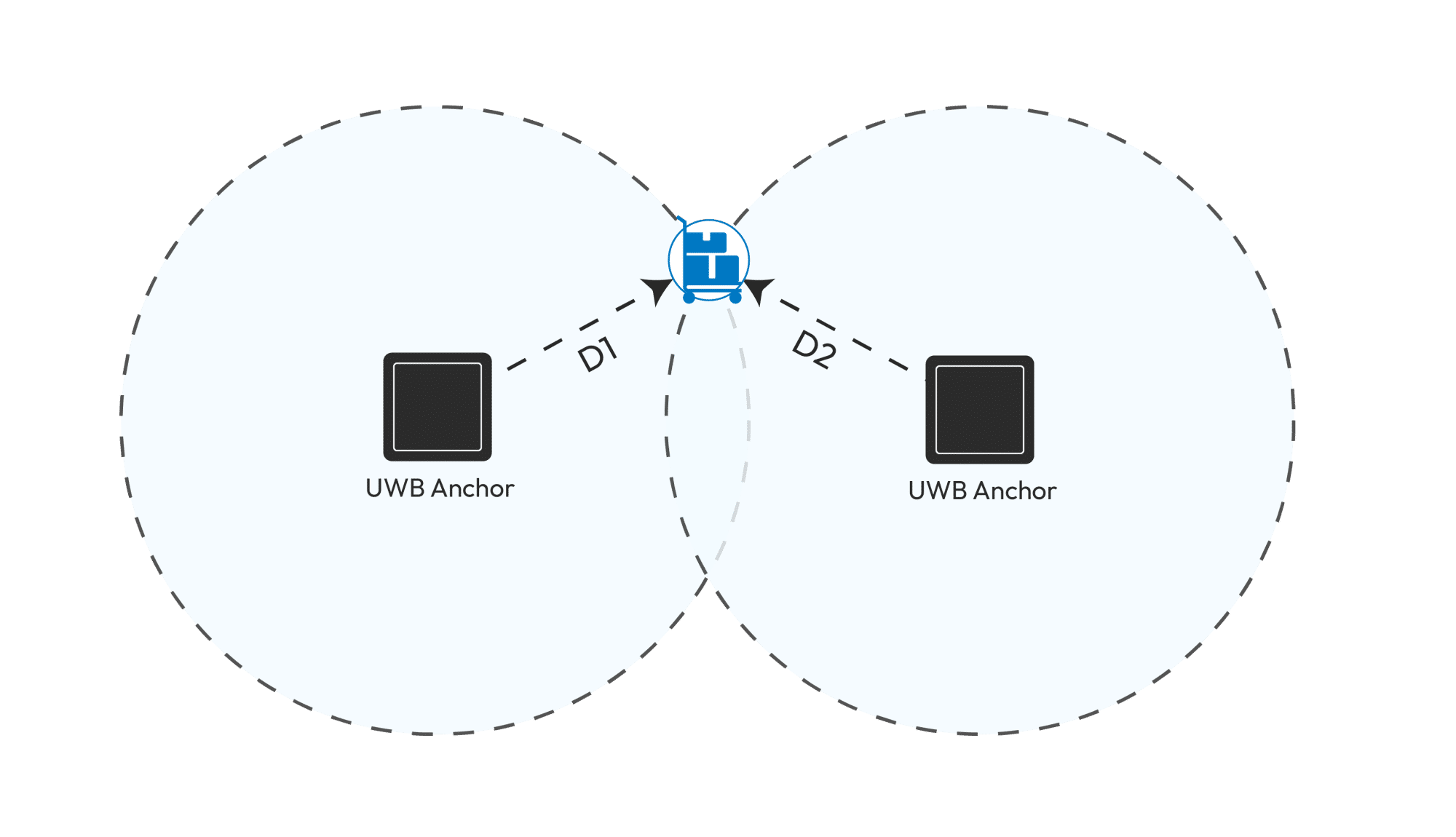
تحديد المواقع ثنائي الأبعاد:
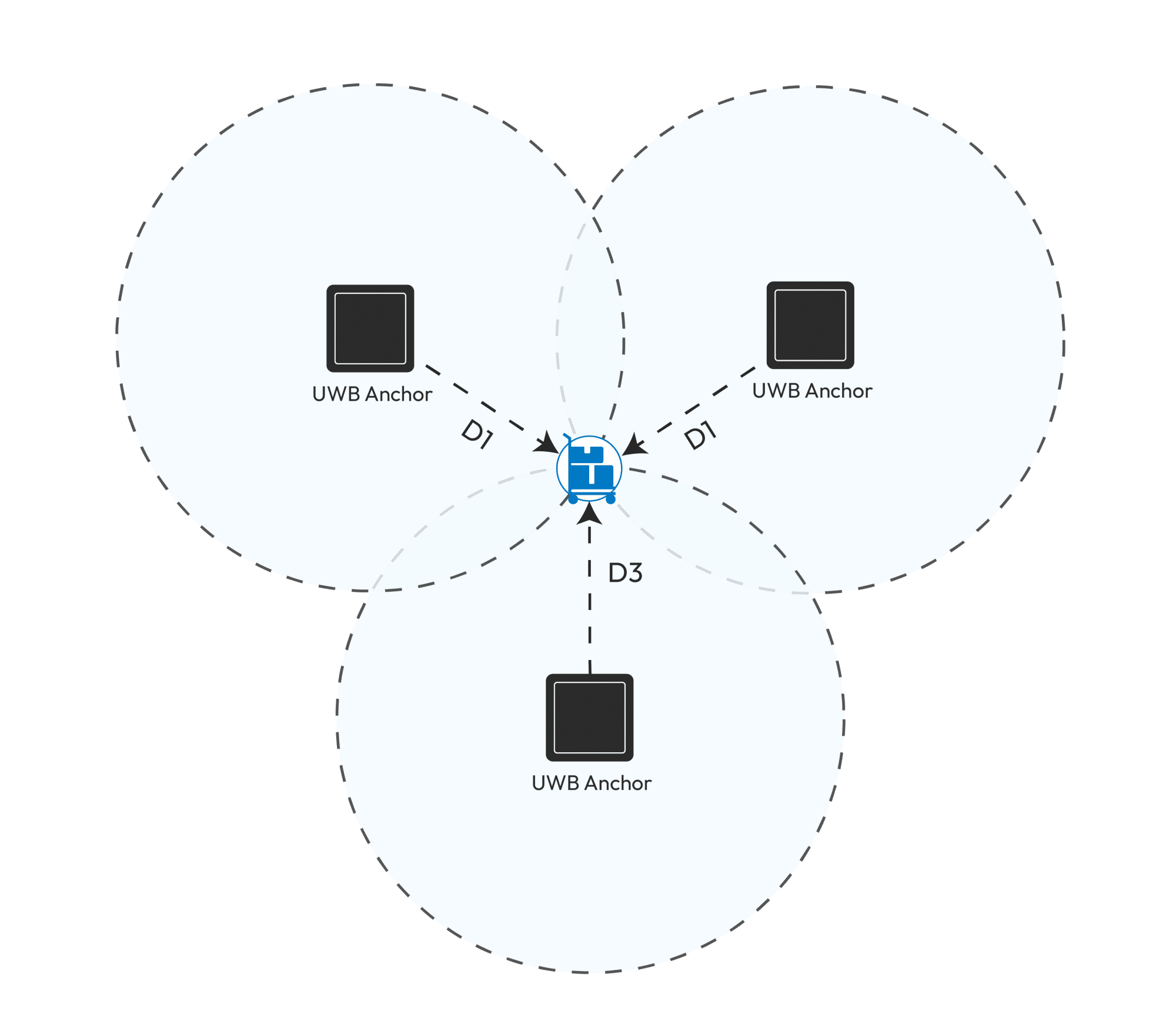
تحديد موقع TDoA
تحديد موقع الهدف بتقنية TDoA هو تحديد موقع الهدف من خلال رصد الفرق الزمني المطلق بين وصول الإشارات إلى مرساة أو وحدتي هوائي مختلفتين، بدلاً من رصد وقت وصولها. هذا يُقلل من متطلبات مزامنة الوقت بين مصدر الإشارة وكل مرساة مراقبة، ولكنه يزيد من متطلبات مزامنة الوقت بين المراسي. يمكن رصد هاتين الهاتين باستخدام ثلاث مرساة مختلفة، ويقع جهاز التتبع المتحرك عند تقاطع القطع الزائد المُحدد بواسطة هاتين الهاتين.

ميزة TDoA هي تقليل عدد الاتصالات لتحديد موقع واحد بشكل ملحوظ، كما أنها تتميز بدقة أعلى من ToA. مع ذلك، يعتمد هذا النوع من تحديد المواقع على انتشار الموجات، ويمكن أن يؤدي خطأ الساعة المتأصل البالغ 1 نانوثانية إلى خطأ في المسافة قدره 30 سم. لذلك، يجب مزامنة ساعات كل مرساة بدقة. كما أن بناء نظام مزامنة دقيق بمسافات كبيرة نسبيًا أمر مكلف للغاية.
هناك نوعان من مزامنة الوقت:
أحدها هو استخدام التوصيلات السلكية، التي يمكن أن تحقق دقة مزامنة تبلغ 0.1 نانوثانية، ولكنها تزيد من تعقيد وتكلفة صيانة الشبكة وبنائها. علاوة على ذلك، تتطلب كابلًا مخصصًا (مثل إيثرنت) لمزامنة الساعة، وهو أمر مكلف أيضًا.
الطريقة الأخرى هي الاتصالات اللاسلكية، التي تحقق دقة مزامنة تبلغ 0.25 نانوثانية، وهي أقل بقليل من الاتصالات السلكية، إلا أن النظام بسيط نسبيًا. تحتاج بوابة تحديد الموقع فقط إلى مصدر طاقة، ويمكن إرجاع البيانات عبر شبكات WiFi أو LoRa أو Ethernet، مما يقلل التكلفة بشكل كبير.
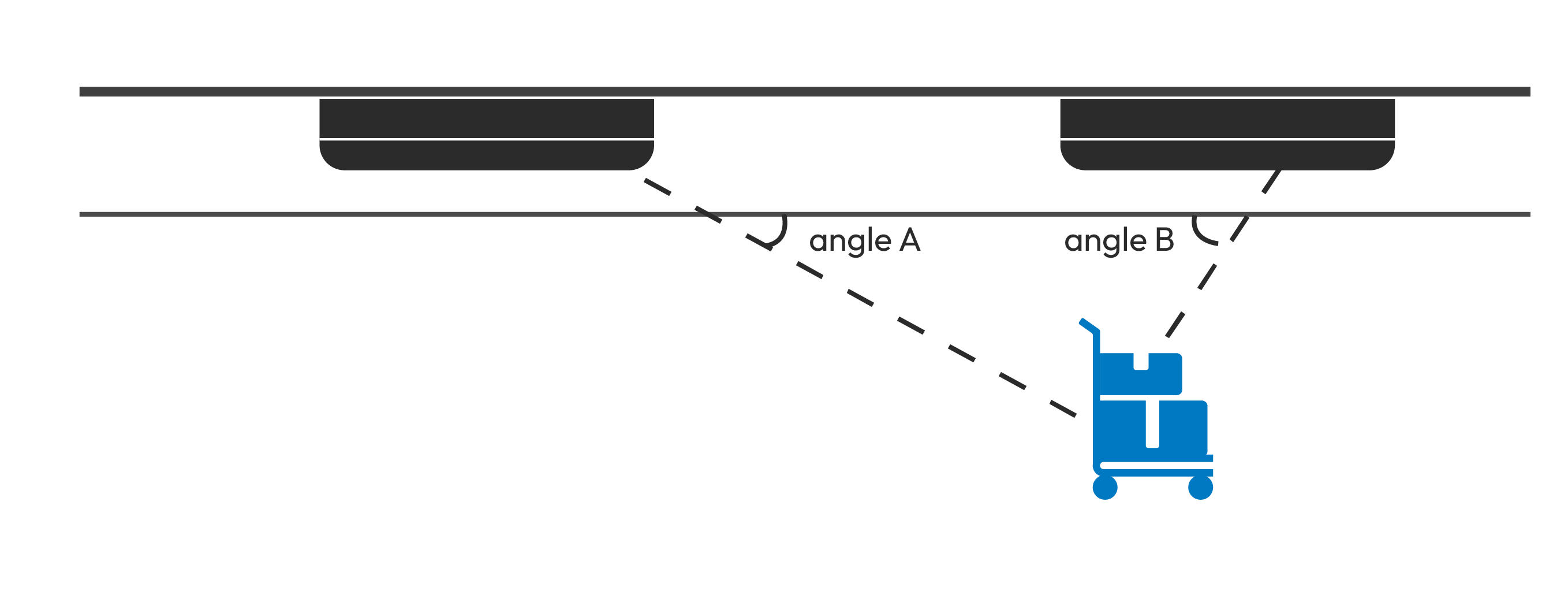
تحديد موقع زاوية الهجوم
يعتمد تحديد موضع زاوية الوصول (AoA) بشكل عام على الفرق في الطور بين الإشارات، ولكن لا يتم استخدامه بمفرده في كثير من الأحيان لأن زاوية الوصول (AoA) تعاني من مشكلة في الدقة الزاوية، مما يعني أن دقة تحديد الموضع تزداد سوءًا مع زيادة المسافة من المرساة.
يمكن لزاوية الهجوم (AoA) أن تتكامل مع مدى زمن الرحلة (ToF) لتحديد الموقع. في هذا الوضع، يمكننا استخدام مرساة واحدة لتحديد الموقع.

من الممكن أيضًا أن يحقق مرساة اثنين تحديد المواقع من خلال AoA
وضع التموضع واستهلاك الطاقة
سنقارن بشكل أساسي استهلاك الطاقة في وضعي ToF وTDoA. في وضع ToF، يقيس متتبع UWB المسافة مع كل مرساة على حدة، ويتطلب ذلك عدة تصنيفات. عادةً، يستغرق النطاق الواحد أكثر من 5 مللي ثانية. لتحديد الموقع في TDoA، لا يحتاج متتبع UWB سوى إرسال رسالة لإكمال التحديد. عادةً، يستغرق الأمر أقل من 0.5 مللي ثانية من التحضير إلى الإرسال، ويستهلك طاقة أقل بكثير من وضع ToF.
العوامل البيئية
هناك العديد من العوامل البيئية، وأكثرها شيوعًا هي التموضع داخل المنطقة والتموضع خارج المنطقة؛
بما أن خوارزمية TDoA تعتمد على فرق زمن وصول الإشارة، فإنها عادةً ما تستخدم خوارزمية زائدية تُحوّل فرق زمن الوصول إلى فرق المسافة. ويؤدي قصور هذه الخوارزمية إلى ارتفاع دقة تحديد الموقع في المنطقة التي تغطيها المراسي، وانخفاضها نسبيًا خارجها. في البيئات المعقدة، مثل محطات الطاقة، يواجه النظام صعوبة كبيرة في النشر، ويصعب استخدام خوارزمية TDoA في تحديد المواقع لتلبية احتياجات التطبيقات. في هذا الوضع، يمكن استخدام ToF، أو TDoA مع AoA.
الفصل الخامس
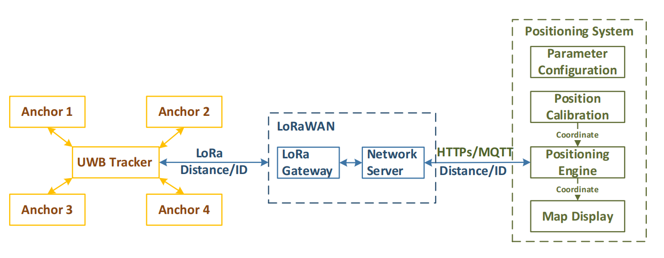
حل تحديد المواقع UWB المستند إلى LoRaWAN
يقدم هذا الفصل الجهاز والنظرية ذات الصلة بكيفية عمل النظام.
- مرساة UWB: يُعلن عن رسائل منارة لتحديد المسافة باستخدام أجهزة التتبع. يعمل بالبطارية، ويدوم لخمس سنوات.
- متتبع UWB: يستقبل رسائل المنارة ويتحرك مع المرساة بشكل دوري. يعمل بالبطارية.
- بوابة LoRaWAN: يرسل رسائل منارات إلى جميع المراسي وأجهزة التتبع لمزامنة الساعة واستقبال رسائل المسافة من أجهزة التتبع.
- الخادم: استخدم معلومات المسافة وإحداثيات المرساة لحساب موضع المتتبعين كما هو موضح في القسم 4.1يتم استخدام الخادم أيضًا لتكوين المرساة وجهاز التتبع، ومعايرة موضع المرساة والعمل كمحرك تحديد المواقع.
الفصل السادس
حول النطاق
طريقة تحديد النطاق
في نظام تحديد المدى، هناك طريقتان لتحديد المدى: تحديد المدى أحادي الجانب في اتجاهين (SS-TWR) وتحديد المدى ثنائي الجانب في اتجاهين (SD-TWR).
SS-TWR
يوضح الشكل 2، وهو رسم تخطيطي لمبدأ SS-TWR، المبدأ الأساسي لتحديد المدى ثنائي الاتجاه أحادي الجانب. يرسل الجهاز أ نبضة إلى الجهاز ب. بعد فترة Tround1، يستقبل النبضة المُعادة من الجهاز ب. بافتراض أن زمن الرحلة هو Tprop، يُمكن حسابه تقريبًا على النحو التالي:
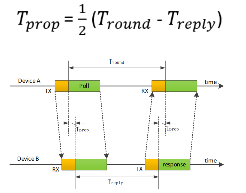
نظرًا لأن الجهاز A والجهاز B يستخدمان مصادر ساعة مستقلة، فسوف يكون للساعات انحراف معين، وهو أمر غير مقبول أيضًا بالنسبة لسرعة الضوء.
SD-TWR
تحديد المدى ثنائي الاتجاه ثنائي الجانب هو طريقة تحديد مدى ممتدة لتحديد المدى ثنائي الاتجاه من جانب الإشارة. يسجل هذا التحديد زمن رحلتين ذهابًا وإيابًا، ثم يحصل في النهاية على زمن الرحلة. على الرغم من أنه يزيد من زمن الاستجابة، إلا أنه يقلل من خطأ تحديد المدى. كما هو موضح في الشكل 3 (الرسم التخطيطي) لمبدأ DS-TWR، فإن المبادئ الأساسية هي كما يلي:
- يقوم الجهاز أ بإرسال نبضة إلى الجهاز ب؛
- بعد أن يستقبل الجهاز B النبضة، فإنه يؤخرها إلى Treply1 ويرسل نبضة مرة أخرى؛
- بعد الجولة 1، يستقبل الجهاز A نبضة الرد المرسلة بواسطة الجهاز B؛
- يقوم الجهاز A بتأخير Treply2 ثم يقوم بإرسال نبضة أخرى إلى الجهاز B؛
- يستقبل الجهاز B النبضة النهائية من A بعد الجولة الثانية.
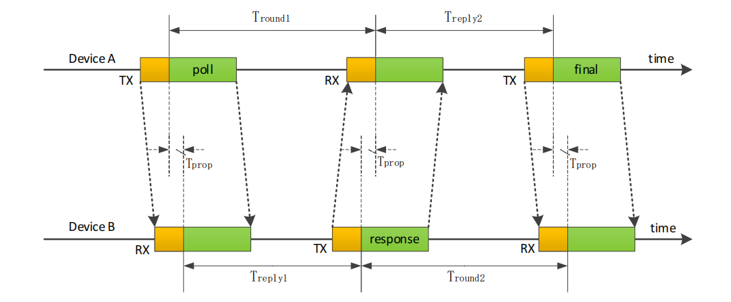
يعد تحديد المدى DS-TWR اتصالاً إضافيًا يعتمد على تحديد المدى SS-TWR، ويمكن لوقت الاتصالين إلغاء الخطأ الناتج عن إزاحة الساعة.
الخطأ الذي تسببه الساعة باستخدام طريقة تحديد المدى DS هو:

يعتمد خطأ طريقة التقييم هذه بشكل أساسي على العوامل التالية:
- خطأ الساعة للجهازين A و B؛
- متوسط وقت التأخير لمعالجة الجهاز.
بافتراض أن دقة ساعة الجهازين (أ) و(ب) هي ٢٠ جزءًا في المليون (ضعيف)، وأن جزءًا واحدًا في المليون هو جزء من مليون، فإن Ka وKb هما إما ٠٫٩٩٩٩٨ أو ١٫٠٠٠٠٢، وka وkb هما نسبة التردد الفعلي إلى التردد المتوقع لساعتي الجهازين (أ) و(ب) على التوالي. المسافة بين الجهازين (أ) و(ب) ١٠٠ متر، وزمن انتقال الموجات الكهرومغناطيسية هو ٣٣٣ نانوثانية. عندئذٍ، يكون الخطأ الناتج عن الساعة ٢٠ × ٣٣٣ × ١٠^(-٩) ثانية، وخطأ القياس ٢٫٢ ملم، وهو خطأ يمكن تجاهله.
تحليل خطأ النطاق
العوامل التي تؤدي إلى أخطاء تحديد المدى هي الاضطرابات البيئية، وانسداد جسم الإنسان، وانسداد جسم معدني، ودقة الوقت، والحد الأدنى من حبيبات الوقت.
سيناريوهات النطاق النموذجية
لتلبية متطلبات حالات استخدام النطاق الدقيق اللاسلكي المختلفة، هناك ثلاثة أوضاع رئيسية: النطاق من نقطة إلى نقطة، والنطاق من نقطة إلى نقاط متعددة، والنطاق في المساحة الحرة.
يقدم ما يلي بشكل أساسي وضعي تحديد المدى من نقطة إلى نقاط متعددة وتحديد المدى في المساحة الحرة.
تحديد المدى من نقطة إلى عدة نقاط
يُستخدم هذا الجهاز بشكل رئيسي لقياس المسافة بين جهازين. يُعدّ هذا النوع من قياس المسافة الأبسط والأكثر دقة وسهولة الاستخدام. ولأن قياس المسافة هو الوظيفة الأساسية، يُمكن دمجه مع طرق أخرى.
بعض التطبيقات النموذجية هي:
- عندما تكون المركبة قيد التشغيل، فإنها تحتاج إلى معرفة موقعها الدقيق، والذي يمكن القيام به من خلال قياس المسافة؛
- عندما يكون السجين في الإفراج المشروط لتلقي العلاج الطبي، يمكن لحراس السجن التحكم في السجين ضمن مسافة آمنة من خلال قياس المسافة بدقة، ويمكن للمسؤولين أيضًا استخدام المنصة لمنع المحسوبية؛
- قياس المسافة بدقة بين الطائرات بدون طيار والأشخاص؛
- يمكن للمجموعات السياحية التحكم في المسافة بين كل شخص ومرشد الرحلة من خلال UWB لضمان عدم ضياع أي شخص.
تحديد المدى في الفضاء الحر
يُعدّ تحديد المدى في الفضاء الحرّ أسلوبًا خاصًا نسبيًا. والسبب الرئيسي هو أن جميع الأهداف تتحرك في الفضاء. قبل كل تحديد مدى، يحتاج الجهاز إلى معرفة الظروف المحيطة؛ فإذا كان هناك العديد من أهداف التحديد، من الضروري توزيعها جيدًا لتجنب التداخل بينها ومنعها من تحديد المدى.
يتم استخدام القياس في الفضاء الحر بشكل أساسي للغرضين التاليين:
شبكة العلاقات المكانية:
على سبيل المثال، يمكن لتشكيلات الطائرات بدون طيار أن تُشكّل شبكة ذاتية التنظيم بناءً على المسافة المكانية بين جميع الأهداف. في حال عدم وجود نظام GNSS، يُمكن استخدام النطاق العريض للغاية (UWB) لتكوين شبكة علاقات موقعية للتشكيلات المكانية؛
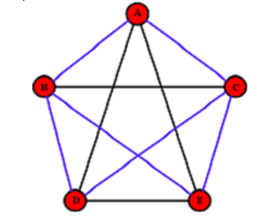
إذا تم تطبيق هذا النظام في شبكة Mesh للاتصالات اللاسلكية، فيمكنه أيضًا توفير معلمات المسافة لشبكة Mesh لاتخاذ القرارات.
مضاد للتصادم:
على سبيل المثال، يمكن لقاطرة الصيانة التي تعمل على مسار القطار أن تتمتع بضمانة أخرى تعتمد على قياس المسافة الديناميكي هذا.
الفصل السابع
تصميم المخطط
نظام منع الاصطدام ونظام تحديد المواقع:
يُعرَّف الجهاز المُثبَّت على نظام منع الاصطدام بأنه بوابة UWB، قابلة للتشغيل من مصدر خارجي. أما الجهاز الذي يرتديه الشخص فهو جهاز تتبُّع UWB، يعمل ببطارية قابلة لإعادة الشحن.
محرك تحديد المواقع:
هذا لحساب موقع أجهزة تحديد المواقع. يستخدم محرك تحديد المواقع الموقع النسبي للبوابة على الخريطة، والمسافة بين جهاز تتبع النطاق العريض للغاية والبوابة، لتحديد موقع جهاز تتبع النطاق العريض للغاية وإحداثيات موقع الإخراج.
معايرة الموضع:
حدد موقع البوابة على الخريطة، مثل تحديد نقطة البداية وموقع البوابات. يجب أن تكون البوابة ثابتة وغير قابلة للتحريك بشكل عشوائي.
عرض الخريطة:
يمكن للعملاء تحميل ملفات الخريطة الخاصة بهم وتوفير معلومات الأصل المقابلة في معايرة الموضع، وعرض الموضع في الوقت الحقيقي لجهاز تحديد المواقع على الخريطة المسطحة.
تصميم مخطط نظام منع الاصطدام
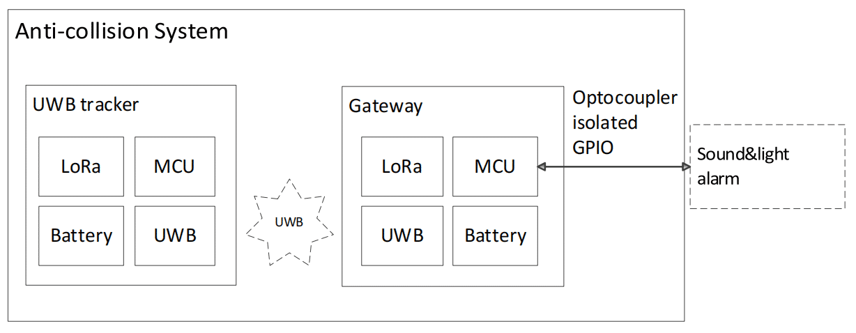
معلومات عن جهاز تتبع النطاق العريض للغاية (UWB). يقيس جهاز تتبع النطاق العريض للغاية المسافة كل 4 ثوانٍ. عند الاقتراب من البوابة، يقيس الجهاز المسافة كل ثانية واحدة لتوفير الطاقة وإطالة وقت الاستعداد.
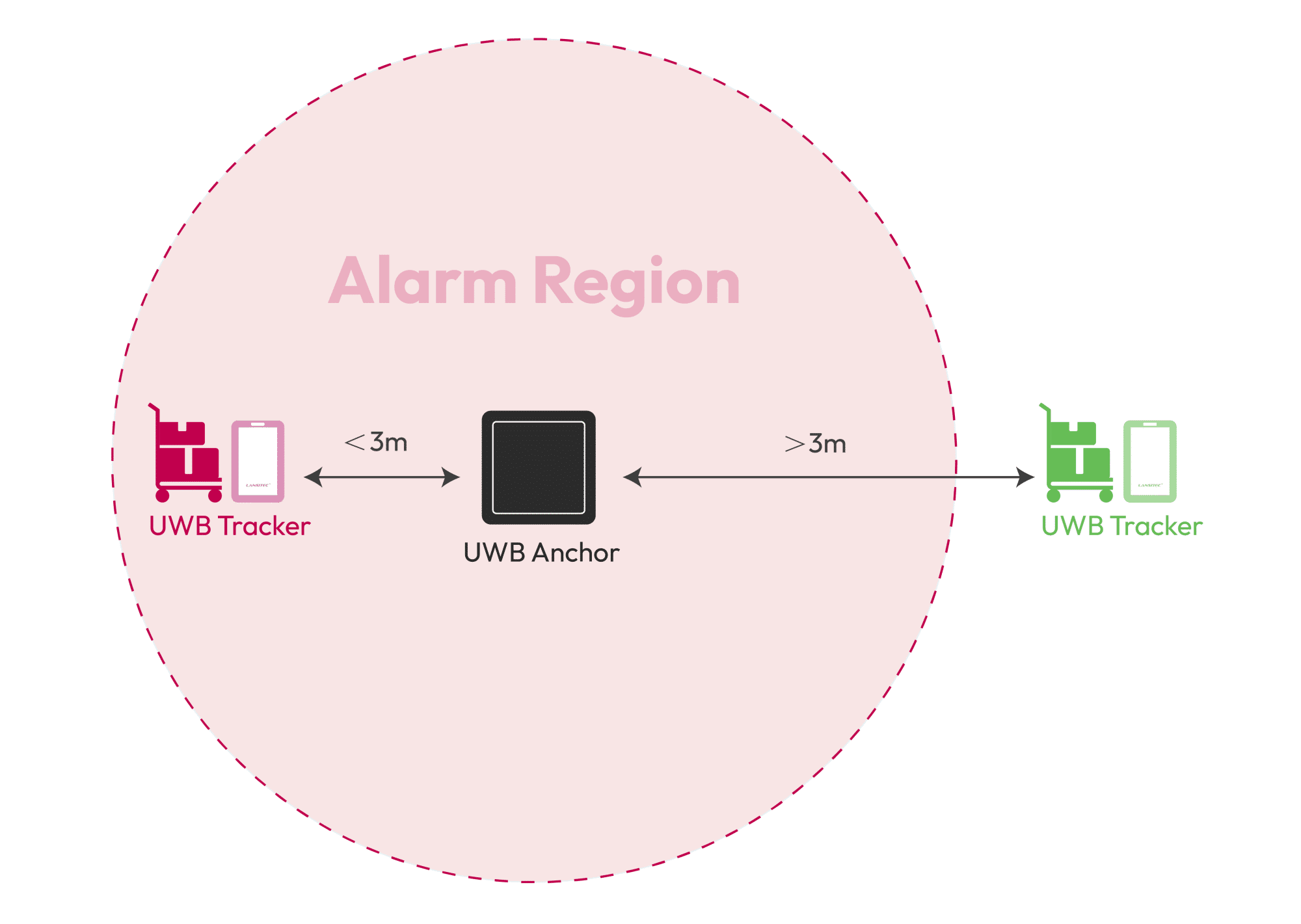
تتميز البوابة بواجهة إدخال/إخراج مع عزل بصري. عندما تكون المسافة بين جهاز تتبع النطاق العريض الفائق والبوابة أقل من 3 أمتار، تُخرج البوابة طاقة خرج عالية المستوى. يمكن توصيل واجهة الإدخال/الإخراج المعزولة بجهاز إنذار صوتي وضوئي خارجي.
يظهر تقسيم المنطقة في الشكل 6: تقسيم مساحة نظام منع الاصطدام. (الصفحة التالية)
تصميم مخطط نظام تحديد المواقع
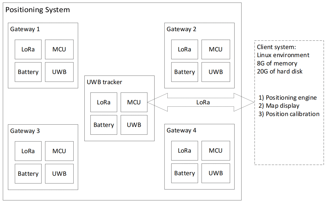
يحتوي كلٌّ من البوابة وجهاز تتبّع النطاق العريض للغاية (UWB) على وحدات UWB وLoRa. وحدة UWB مخصصة لقياس المسافة وتحديد المواقع، بينما وحدة LoRa هي .
ينقل متتبع UWB المسافة بين متتبع UWB والبوابة والمعرف والمعلمات الأخرى إلى نظام التطبيق من خلال LoRa.
يحتوي نظام التطبيق على ثلاث وحدات برمجية: محرك تحديد المواقع، وعرض الخرائط، ومعايرة المواقع. يجب تشغيل هذه الوحدات البرمجية في بيئة لينكس، أو يمكن أيضًا تثبيت جهاز افتراضي يعمل بنظام لينكس في نظام ويندوز. تتطلب بيئة لينكس ذاكرة وصول عشوائي (RAM) بسعة 8 جيجابايت على الأقل وقرصًا صلبًا بسعة 20 جيجابايت.
سير عمل النظام
سير عمل نظام منع الاصطدام:
- تستخدم البوابة مصدر طاقة خارجي، لذا فهي جاهزة دائمًا لاختبار البيانات.
- تستخدم البوابة وجهاز تعقب UWB تقنية DS-TWR لقياس المسافة.
- يقوم متتبع UWB بقياس المسافة مع البوابة بشكل دوري (4 ثوانٍ).
- يكتشف متعقب UWB بوابة قريبة ويقيس المسافة بها، ثم يغير دورة قياس المسافة الخاصة به إلى 1 ثانية.
- تقوم البوابة بإخراج إشارة إنذار (إنذار صوتي وضوئي) بناءً على المسافة من متعقب UWB.
سير عمل نظام تحديد المواقع:
- قم بتشغيل برنامج معايرة الموضع لمعايرة موضع التثبيت الفعلي للبوابة.
- قم بتشغيل برنامج محرك تحديد المواقع لحساب معلومات الموقع لمتعقب UWB استنادًا إلى المسافة بين متعقب UWB والبوابة.
- تستخدم البوابة وجهاز تعقب UWB تقنية DS-TWR لقياس المسافة.
- يقوم متعقب UWB بقياس المسافة بشكل دوري باستخدام بوابات متعددة قريبة.
- يرسل متعقب UWB المسافة من بوابات متعددة إلى محرك تحديد المواقع في شكل LoRa.
- يتم إرسال معلومات الموقع المحسوبة بواسطة محرك تحديد المواقع إلى برنامج عرض الخريطة لعرضها.
حساب تحديد المواقع
يمكن لمحرك تحديد المواقع حساب معلومات موقع متتبع UWB استنادًا إلى المسافة بين البوابة ومتتبع UWB وإحداثيات موقع البوابة باستخدام التثليث، كما هو موضح في حساب الموقع المثلثي.


