Introduction
LoRaWAN (Long Range Wide Area Network) technology has revolutionized the Internet of Things (IoT) landscape, providing a means to connect devices over long distances without the need for extensive power consumption. This groundbreaking innovation has propelled advancements across various sectors such as smart cities, agriculture, supply chain management, and environmental monitoring.
Understanding how factors influence the range of LoRaWAN is critical for network planning, expansion, and performance optimization, making it a topic of substantial technical and commercial interest.
The ability to maximize the range of LoRaWAN networks enables the deployment of wireless sensor networks across vast geographical expanses, a feat that was once both financially and logistically prohibitive. However, achieving this extended coverage is not without its challenges. The range of a LoRaWAN network is subject to multiple influences that derive from technical specifications, environmental conditions, regulatory boundaries, and the inherent characteristics of the radio frequency propagation.
This article aims to delve into the myriad of factors affecting the range of LoRaWAN networks. It will explore the technical underpinnings of the protocol, the interplay of different environmental parameters, the significance of network topology, and the constraints imposed by adherence to regulatory frameworks. Through this thorough examination, we will equip readers with a comprehensive understanding of the determinants of LoRaWAN range, reinforced by real-world case studies and applications.
Understanding LoRaWAN
Before delving into the various factors that influence the range of a LoRaWAN network, it is essential to understand the fundamental characteristics of this technology and the principles behind its operation. LoRaWAN stands at the intersection of two key components: LoRa, the physical layer or the modulation technique that encodes data into radio waves, and LoRaWAN, the network protocol that defines the system architecture and communication protocols.
- LoRa: The Physical Layer
LoRa is derived from “Long Range” and is a spread spectrum modulation technique that employs Chirp Spread Spectrum (CSS) technology. This method is known for maintaining communication over large distances, achieving ranges that can extend several kilometers in open, rural areas. One of the core benefits of LoRa modulation is its resilience to signal interference and its low power requirements, allowing battery-operated devices to function for years without a recharge. - LoRaWAN: The Network Protocol
LoRaWAN defines the communication protocol and system architecture for the network while utilizing the LoRa physical layer. It is a media access control (MAC) layer protocol that maintains network integrity and security. LoRaWAN enables bi-directional communication, a crucial feature for IoT devices that need to send data (such as sensor readings) and receive commands (like actuator control messages).
How LoRaWAN Works
- LoRaWAN allows devices to communicate with Internet-connected applications over long-range wireless connections. The network architecture is typically laid out in a star topology, where end devices use single-hop wireless communication to one or many LoRaWAN gateways, all connected to a central network server.
- The technology operates in the unlicensed ISM (Industrial, Scientific, and Medical) band, which varies by region (e.g., 868 MHz in Europe, 915 MHz in North America). LoRaWAN networks can handle millions of messages per day, making them scalable and versatile for various applications.
Criteria for Describing a Network in Radio Technology
There are basically three characteristics that can be used to describe a network in radio technology:
- Range
- Data transfer speed
- Energy consumption
It’s hard to place equal importance on all three criteria because the laws of physics have clear limits on this. For example, LoRaWAN can transmit data over long distances with relatively little energy, but at very low data rates.
Wi-Fi and Bluetooth can achieve high data rates, but the power consumption is relatively high and the range is small. All smartphone users are only too familiar with this hunger for energy. The base stations of the big telecom operators provide high data rates and relatively long distances but must provide a lot of energy to do so. Therefore, the power supply is an essential factor in such installations.


Power Transmission Balance
The power transmission balance indicates the quality of the radio transmission channel. It can be calculated by adding transmitting power, receiver sensitivity, antenna gain, and free space path loss (FSPL).
LoRaWAN calculates the power transmission balance.
Path loss represents the energy lost in free space over a distance between the transmitter and receiver. The farther away TX is from Rx, the lower the energy is.
Path loss is usually expressed as

Where means:
FSPL = Free Space Path Loss;
d = distance between TX and Rx in meters;
f = frequency in Hertz
There is also a widely used logarithmic formula for free-space attenuation:

Double the distance (d) means a loss of 6dB.
At the receiving end (Rx), the sensitivity of the receiver end is the factor that affects the power transmission balance. The Rx sensitivity describes the minimum possible received power and thermal noise tolerance:

Where means:
BW = bandwidth in Hz;
NF = noise factor in dB;
SNR = signal-to-noise ratio.
It tells how far the signal must lie with the noise.
LoRa Device’s Rx is more sensitive and, therefore, better than WLAN. The extreme case of path loss without considering antenna gain and other types of free-space attenuation:

An example of calculating a LoRaWAN power transmission balance:
TX power = 14 dBm;
BW = 125KHz = 10log10 (125000) = 51;
NF = 6dB (the gateways in LoRaWAN networks have lower NF values);
SNR = -20 (for SF = 12).
Entering these numbers in Formula ③ results in an Rx sensitivity of -137 dBm
Rx sensitivity = – 174 + 51 + 6 – 20 = -137 dBm
The power transmission balance can then be calculated as follows using Formula:
Power transmission balance = -137dB – 14dB = -151dB
With the specified values, the LoRaWAN range power transmission balance is 151 dB, so it can overcome distances of up to 800 km under optimal conditions (pure free-space attenuation). The LoRaWAN range is 702 km at the world record.
At Lansitec the record is 20km:
- Gateway is installed on top of a 30m building
- The tracker is on a ship in the sea
- TX power = 20dBm
Technical Factors Affecting LoRaWAN Range
The range of a LoRaWAN network is not simply determined by a single element but is the cumulative result of various technical components. These encompass aspects of the transmission power, receiver sensitivity, and antenna characteristics, which together shape the fundamental capacity of a LoRaWAN network to transmit data over distances.
TX Power is vital when determining how far the radio waves can travel. Higher power can equate to longer ranges; however, this comes with greater energy consumption, affecting device battery life. Additionally, regulatory limits often cap the maximum allowable TX Power to prevent interference with other wireless technologies.
- Regulatory Restrictions: Different countries and regions have unique regulations governing transmission power. For example, in Europe, under the ETSI regulations, the maximum transmission power for LoRaWAN devices is typically limited to 14 dBm in the 868 MHz ISM band.
- Power Amplification: Some LoRaWAN devices may include power amplifiers to increase their transmission power, but these are constrained by legal limits and the trade-off with battery life.
A more sensitive receiver increases LoRaWAN range as it can pick up weaker signals that would otherwise be lost due to path loss and environmental factors.
- Quality and Design of Receivers: High-quality receivers with better noise figures improve system sensitivity. This is critical in scenarios where signals must be detected at considerable distances or in challenging conditions.
- Impact on Network Design: Implementing receivers with high sensitivity could potentially reduce the number of gateways needed in a LoRaWAN deployment since each gateway can detect and process signals from more distant devices.
Antenna Type and Placement
The antenna is a crucial element of the LoRaWAN hardware configuration. Its design, placement, and the surrounding environment can significantly impact network range.
- Antenna Gain: The gain of an antenna reflects its directivity and efficiency. A higher-gain antenna will focus energy more effectively in a particular direction, possibly increasing range. However, antennas with high gain might also have narrower beam widths, which can be a drawback in some deployment scenarios.
- Antenna Type: Omni-directional antennas radiate power uniformly in all horizontal directions, whereas directional antennas focus power in a specific direction. The choice between these types depends on the particular application and the area that needs coverage.
- Placement and Environment: The location of the antenna can be as important as its design. Antennas should be mounted clear of obstructions with a good line of sight to the area of coverage. Buildings, foliage, and terrain can all impact signal propagation, thus affecting the range.
Free space attenuation factor
By doubling the distance, LoRa free-space attenuation increases by 6dB, so radio propagation attenuation follows a logarithmic function (see Formula below).
- FSPL= Free Space Path Loss;
d = distance between TX and Rx in meters; f = frequency in Hertz
[FSPL (dB) = 20log10 (d) + 20log10 (f) -147.55].
Besides the energy loss caused by the LoRaWAN range, the reflection and refraction of radio waves on objects can also cause radio waves to overlap.
Environmental Factors Impacting LoRaWAN Range
The environment in which a LoRaWAN network operates plays a significant role in its effective range. Factors such as terrain, man-made structures, and weather can affect signal propagation, presenting challenges that must be navigated to maintain good network performance.
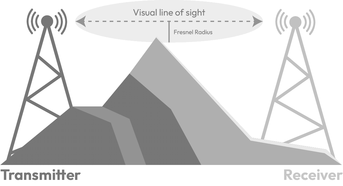
- Terrain——Fresnel zone factor.
- The physical geography of the landscape can markedly determine the propagation of radio waves. LoRaWAN signals can travel farther in open, flat areas than in hilly or mountainous regions where the line of sight may be frequently obstructed.
- The Fresnel zone is a concept in wireless communication that refers to an elliptical region outside the direct line of sight between two communication devices. This zone is important in wireless communication, as obstacles within this area can cause signal scattering and multipath effects, which can affect communication quality. Therefore, in the planning and installation of wireless communication systems, the impact of the Fresnel zone on signal transmission needs to be considered, and ensuring sufficient clearance space along the communication path is important.
- It is essential to establish as a straight line of sight between transmitter and receiver as possible if you want to cover long distances effectively and get a good power transmission balance. Certain areas of space between the lines of sight of the radio transmission are Fresnel regions. The propagation of the waves will be negatively affected if there are objects in these areas, despite the usual visual contact between the transmitting and receiving antennas. For each object in the Fresnel belt, the signal level drops and the LoRaWAN range shrinks (see Figure 3 Fresnel zone factor affert the LoraWAN range). So it is usually better to install a LoRaWAN building on top of a building. The higher the better.
An omnidirectional antenna is a common technology to be used in LoRaWAN range networks. Thus, radiated energy diffuses into the horizontal plane, and the network nodes and gateways are located there. In Europe, ISM band transmission power is limited to 14 dBm at 868mhz. 2.15dBi is the maximum antenna gain.
Man-Made Structures——Structural damping factor and urban environments
- In urban settings, buildings can both obstruct and reflect radio signals, leading to attenuation (signal loss) and multipath propagation, where signals take multiple paths to reach the receiver, potentially causing interference and reducing the quality of the received signal.
Structural attenuation coefficient structural attenuation, that is, the attenuation of radio signals as they pass through different obstacles, affects the reception of transmitted signals and ensures that the signal range is greatly reduced. For example, the glass attenuation is only 2dB. This affects far less than a concrete wall 30 centimeters thick. The table below shows the various materials and their typical attenuation
Material attenuation |
dB |
|---|---|
|
Glass(6mm) |
0.8 |
Weather and Atmospheric Conditions
- Weather conditions like rain, fog, and humidity can absorb or scatter radio waves, leading to additional signal loss. Although LoRa is more resilient to these effects compared to higher-frequency technologies, significant weather events can still diminish signal strength and, consequently, the range of the network.
- These environmental factors underscore the necessity for comprehensive site surveys and network planning to ensure reliable connectivity across different deployment scenarios. It’s important to consider the potential range implications when installing LoRaWAN infrastructure and to adapt the network design to mitigate environmental impacts.
Network Configuration and Factors Affecting LoRaWAN Range
Network design and configuration choices directly influence the operational extent of a LoRaWAN network. These choices hinge on spreading factors, bandwidth settings, coding rates, and how the network navigates signal interference.
- Spreading Factor (SF)
The Spreading Factor in LoRaWAN modulates the number of chirps per bit of data transmitted. It is a critical parameter that trades off between data rate and range. Higher spreading factors result in lower data rates but allow for a longer range since the signal can be detected over greater distances with a lower signal-to-noise ratio.
- In LoRaWAN networks, the specific setting of the data transfer rate uses spread Factors (SF). The LoRaWAN network uses SF7 to SF12. Due to its chirped spread spectrum modulation and the different phase shift frequencies used in the chirp, the LoRaWAN network is insensitive to interference, multipath propagation and fading. In LoRaWAN range networks, the TX side uses chirp to encode data, while the Rx side uses inverse chirp to decode signals. How many chirps are used per second, the definition of the bit rate, and the amount of energy radiated by each symbol, and the LoRaWAN range that can be achieved have been represented above. For example, the bit rate of SF9 is 1/4 of SF7, which the scalability of LoRaWAN can achieve. The slower the bit rate, the higher the energy and longer airtime, and the greater the range of each data set.
Spreading Factor |
Chips/symbol |
SNR limit |
Time-on-air (10byte packet) |
Bit rate |
|---|---|---|---|---|
|
7 |
128 |
-7.5 |
56ms |
5469bps |
- By using a higher SF, LoRa signals become more robust to interference and can be received across longer distances, albeit with the trade-off of increased airtime and reduced network capacity.
- Bandwidth and Coding Rate
LoRaWAN allows for the adjustment of the bandwidth and coding rate, which affect the LoRa signal’s robustness against noise and interference.
- Bandwidth (BW): A wider bandwidth increases the data rate, reducing the time on air but making the signal more susceptible to noise. Conversely, a smaller bandwidth results in a lower data rate but a more resilient signal.
- Coding Rate (CR): The coding rate defines the ratio of data bits to the total number of bits transmitted, accounting for error-correcting codes. A higher coding rate means more redundant data is transmitted, providing increased resilience to bit errors at the expense of data rate efficiency.
- Channel Interference
LoRaWAN operates in the unlicensed ISM bands, where various other devices and technologies also transmit. The presence of interference from these sources can affect the clarity of the signal and reduce effective range.
- Co-Channel Interference: When numerous devices transmit on the same frequency channel, co-channel interference can occur. LoRa’s use of CSS modulation helps mitigate this issue, but it remains a factor in densely populated networks.
- Duty Cycle Limitations: Some regions impose duty cycle limits on transmissions in the ISM bands. This refers to the ratio of transmission time to total time and is designed to reduce the chance of interference. This limitation can affect the number of messages a device can send and hence influence network design.
Regulatory and Compliance Factors
Regulatory factors are also pivotal when determining the range of a LoRaWAN network due to the limitations and requirements imposed by radio spectrum regulators.
- Frequency Regulations: Different regions have designated specific frequency ranges for the ISM band. Regulatory bodies, such as the FCC in the United States and ETSI in Europe, govern the frequency, power, and duty cycle to balance the needs of various services sharing the spectrum.
- Compliance: Adhering to regulations is essential not just for legal operation but also for ensuring devices are optimized for the frequencies they use. Compliance with these regulations ensures interoperability and network reliability while avoiding penalties or operational disruptions.
Advanced Technological Factors
Emerging advancements in technology offer new solutions to enhance the range and efficiency of LoRaWAN networks.
- Adaptive Data Rate (ADR): ADR optimizes SF and TX power settings for individual nodes, improving power efficiency and overall network performance.
- Network Topology: Deploying additional gateways can improve coverage and capacity. Strategic placement of these gateways, considering terrain and potential obstructions, is essential for network optimization. Through these various network configurations and regulatory considerations, one can fine-tune a LoRaWAN network to maximize its range while adhering to legal requirements and optimizing for network traffic.
Conclusion and Future Outlook
Wrapping up our detailed discussion, we have unraveled the myriad of factors that influence the range of LoRaWAN networks from the technical intricacies of transmission power and receiver sensitivity to the complexities of the environment in which the network is deployed. We have also seen how regulatory considerations and advanced network configurations can further impact the extent and efficiency of network coverage.
In conclusion, maximizing the range of LoRaWAN networks is a dynamic and multifaceted challenge that requires a deep understanding of technical specifications, a careful assessment of the deployment environment, attention to regulatory compliance, and the ability to adapt to ever-advancing technology.
As we look to the future of IoT and connected devices, the lessons learned from these cases and analyses will guide the continued growth and optimisation of LoRaWAN networks across the globe.


